FM-200 Fire System Working Diagram
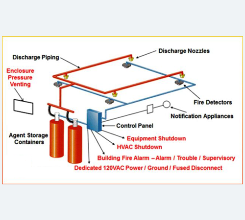
Components of an FM-200 Fire System: Detection System: Smoke detectors, heat detectors, or flame detectors. Control Panel: The central control unit. Cylinder Storage Area: Houses the FM-200 gas cylinders. Discharge Manifold: Distributes the gas to the protected area. Nozzles: Release the FM-200 gas into the protected space. Purging System (Optional): Removes the gas after discharge
Description
Working Principle:
- Detection: When a fire starts, the detection system senses the fire and sends a signal to the control panel.
- Activation: The control panel receives the signal and initiates the system's activation sequence.
- Gas Discharge: The FM-200 gas is released from the cylinders through the discharge manifold and nozzles into the protected area.
- Fire Suppression: The FM-200 gas displaces oxygen, cooling the fire and interrupting the combustion process.
- Purging (Optional): After the fire is extinguished, the purging system removes the FM-200 gas from the protected area.
Diagram Representation:
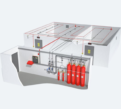
A typical FM-200 fire system diagram would show the following:
- The detection system connected to the control panel.
- The control panel connected to the cylinder storage area.
- The discharge manifold connecting the cylinders to the nozzles.
- The distribution of nozzles within the protected area.
- (Optional) The purging system connected to the protected area.
Similar Products

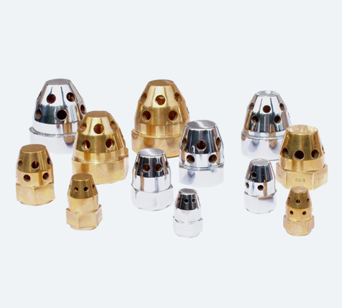
Nozzle

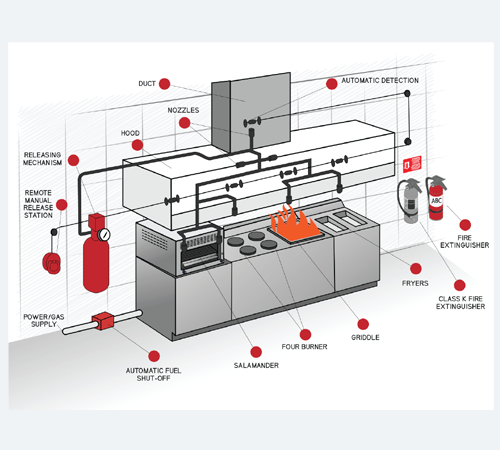
Kitchen Hood Fire Suppression System

Fire Suppression System
