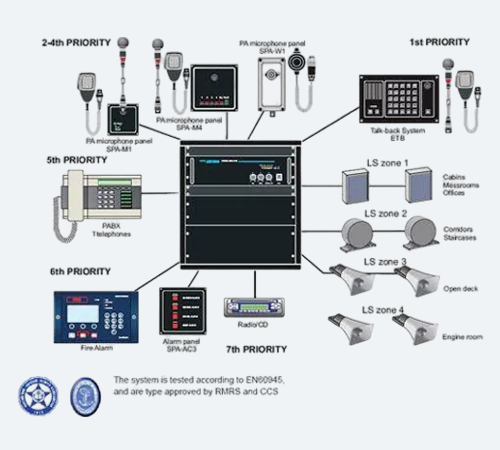
PA System Diagram
A PA system diagram is a blueprint that illustrates how different components of a public address system are interconnected to produce amplified sound. It's essentially a visual representation of the audio signal flow, from input sources to output speakers.
Description
Key Components of a PA System Diagram
A typical PA system diagram will include the following elements:
- Input Sources: Microphones, instruments, or audio players that feed sound into the system.
- Mixer: The central hub where audio signals are combined, adjusted, and routed.
- Signal Processors: Devices that manipulate audio (e.g., equalizers, compressors, effects).
- Power Amplifiers: Boost the audio signal before sending it to the speakers.
- Speakers: Convert amplified electrical signals into sound waves.
- Connections: Cables and wires connecting all components.
Importance of PA System Diagrams
- System Setup: Diagrams help in planning and configuring the system efficiently.
- Troubleshooting: Identifying issues becomes easier by following the signal flow.
- Communication: Diagrams facilitate clear communication between sound engineers.
Similar Products

PA System Diagram

Ceiling Speaker

USB Microphone

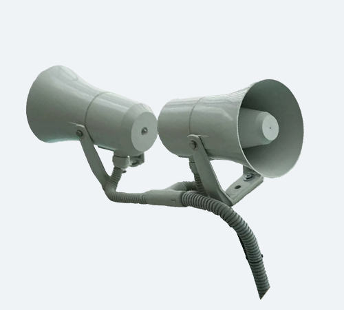
A twin megaphone
